Table of contents
Open Table of contents
The Network Layer
IP Address Classes
An IP address has 32 bits.
IP address = network number : host number
Classes A, B, and C are unicast addresses; D is multicast; E is reserved.
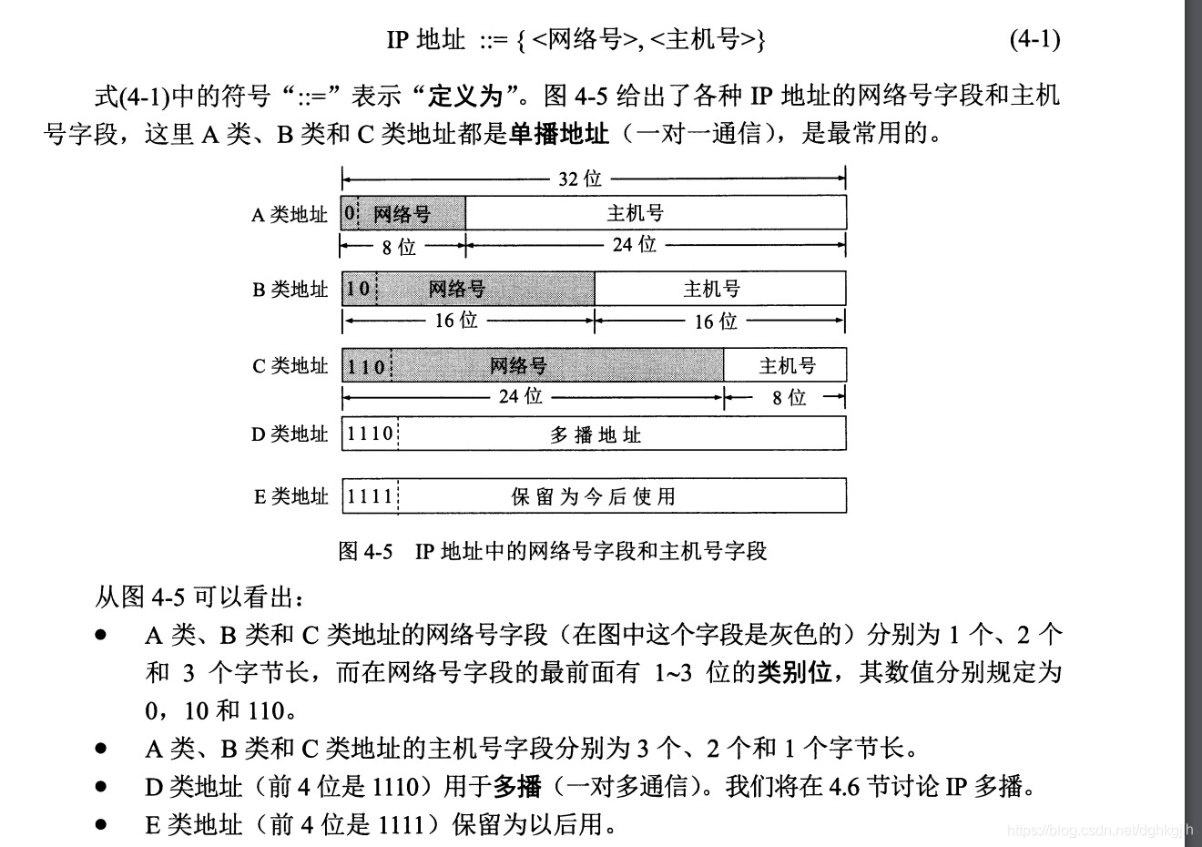
From the figure above, we can calculate:
Total IP addresses = $2^{32}$
Total class A addresses = $2^7 \times 2^{24} = 2^{31}$. The final assignable network number is 127, but 127.x.x.x is reserved, so the largest usable network number is 126. How do we get 127? The network-number range is 0 0000000 to 0 1111111, giving 127. The initial 0 is the fixed network-class bit in the figure above. Other classes are calculated similarly.
Total class B addresses = $2^{14} \times 2^{16} = 2^{30}$. The final assignable network is 191.255.
Total class C addresses = $2^{21} \times 2^8 = 2^{29}$. The final assignable network is 233.255.255.
IP notation: dotted decimal
Each host has an IP address. Routers have two or more because they may connect multiple networks with different network numbers.
Communication between different networks requires forwarding by routers.
Prerequisites for Communication Between Two Hosts
Consider a client communicating with a server. Both have IP addresses. Usually the client knows its own address and obtains the server’s address through DNS resolution of its domain. Both addresses come from an ISP—Internet Service Provider—such as China Mobile, China Unicom, or China Telecom. To connect to the internet, a user needs an IP address and applies to an ISP, which assigns one. This is what happens when setting up home internet.
After obtaining the server address, the client sends information from an application. It passes through the transport layer to the network layer, which adds the destination and source IPs to the IP datagram header. At the data link layer, the datagram is encapsulated into a MAC frame. An important header field is the destination MAC address. Where does that come from?
How Is the Destination MAC Address Obtained? ARP
ARP: Address Resolution Protocol
The IP datagram reaches the data link layer, which adds a frame header and trailer to form a MAC frame. Its destination MAC address is important. Where does it come from?
When passing from the network layer to the data link layer, ARP resolves the MAC address for the destination IP so it can be placed in the frame header.
Every host has an ARP cache containing an IP-to-MAC mapping table.
Resolution Process
-
When A sends an IP datagram to B, A first checks its ARP cache for the destination IP’s MAC address. If present, it uses it directly.
-
If absent, perhaps because A just started or B just joined the LAN, A broadcasts an ARP request. Every host on that LAN receives it.
“Who owns this IP address? Please tell me your MAC address.” Someone replies: “That IP address is mine, and my MAC address is ××××.” Quoted from How Networks Connect, Section 2.5.5.
Hosts whose IP does not match ignore it. The matching host replies with its MAC address and IP, and stores A’s IP and MAC in its own ARP cache. The request itself is sent as a MAC frame.
-
A receives the reply and stores B’s IP and MAC in its ARP cache.
-
ARP cache entries expire and are periodically removed. If B changes its network adapter and therefore its MAC address, after the cache entry expires, A obtains B’s new MAC using the same process when it next communicates with B.
What If They Are on Different Networks?
- ARP resolves IP-to-MAC mappings on the same LAN. Across networks, routers forward traffic. If A sees that B’s IP is outside A’s subnet, it broadcasts to obtain the router’s MAC address. A sets the frame’s destination MAC to the router’s MAC, but the IP datagram still contains B’s destination IP. Remember this.
- The router receives its frame at the data link layer, removes the header and trailer, and passes it to the network layer. Since the destination IP is not its own, it checks whether the destination is on a directly connected subnet. If so, it sends an ARP request on that LAN; otherwise, it forwards according to its routing table to another router. This repeats until B is found, using ARP on different LANs to determine forwarding or destination delivery. At each router-to-router hop, the data link layer changes the frame’s destination MAC to the next router’s MAC.
A Question
In reality, many complex networks lie between A and B, each with N routers. How do routers decide which specific router should forward the packet? Each connects different networks, and the destination may be dozens of routing hops away.
Learn about routing algorithms.
Connection Failures Caused by ARP Issues in AWS VPC
We repeatedly saw this in production: after rebuilding a server with the same IP, deploying code, and starting the JVM for the first time, connections to Redis or Elasticsearch failed. A few restarts fixed it. Destroying the old EC2 instance had also destroyed its network interface by default. Rebuilding created a new interface with the same assigned IP.
The problem is that the recreated interface has a different MAC but the same IP. Before the IP-to-MAC mapping is refreshed in AWS Mapping Service, packets destined for these machines are considered invalid or unknown and dropped. On the EC2 application-server side, this appears as repeated timeouts. Connections succeed only after the new IP-to-MAC mapping is refreshed.
Mapping Service authenticates packets. For details, see AWS re:Invent 2015 | (NET403) Another Day, Another Billion Packets , which explains Mapping Service authentication.
Reddit Q&A: How does ARP works in AWS network
Solution
Retain the network interface when destroying the EC2 instance. When rebuilding, locate the old interface by IP and attach it to the new instance. The interface and MAC stay unchanged, so packets to other servers can arrive normally.
Also note: you may think of sending a gratuitous ARP broadcast from the new EC2 instance to refresh other VPC servers’ ARP caches. This does not work in AWS, which relies on Mapping Service.
IP Datagram Format
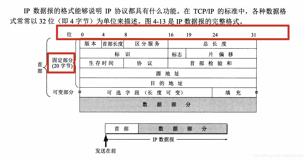
IP datagram = header + data
Unlike a MAC frame, it has no trailer.
IP header (fixed length 20 bytes) = version (4 bits: IPv4 or IPv6) + header length (4 bits) + total length (16 bits) + other fields (64 bits, including identification and TTL in the figure below) + source address (32 bits) + destination address (32 bits)
Source address: source host IP
Destination address: destination host IP
IP Subnets
IP address = network number, subnet number, host number
When A forwards through a router toward 141.14.72.24, that network may contain multiple subnets. The datagram only contains destination IP 141.14.72.24, so the router still needs to determine which subnet to use. This is calculated with the subnet mask.
Subnet Mask Calculation
The subnet mask has four bytes: the first two are all 1s, and the fourth is all 0s. In the format below, … represents the subnet address. AND the third byte of the mask with the third byte of the IP address to obtain it.
11111111 11111111 … 00000000
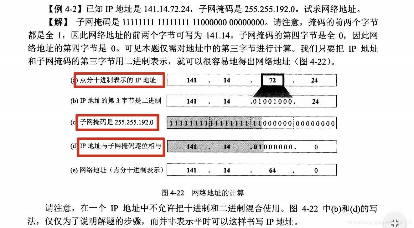
Different subnet masks can produce the same network address.
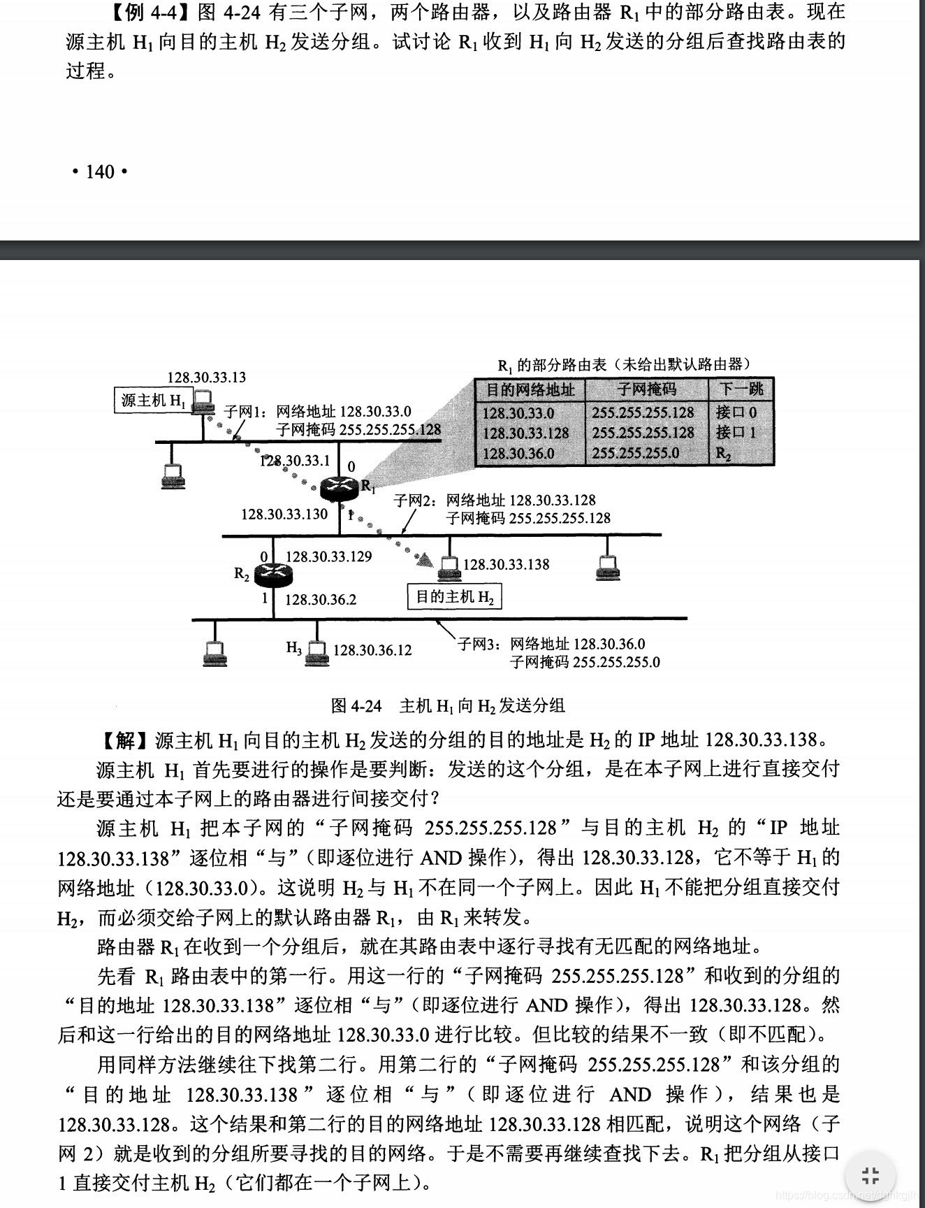
With subnet masks, routing table entries have this structure:
Destination network address + subnet mask + next hop
Routers
Routers Are Middleware at the Network Layer
Search for router operation and how routing tables are constructed.
A router is also a type of computer.
NAT
NAT: Network Address Translation
Ordinary routing does not change source and destination IPs in the datagram. NAT does.
Search for more about NAT.
Understanding the Relationship Between IP and Ethernet (MAC)
- Ethernet determines packet destinations differently from TCP/IP, so the matching addressing method is required to send packets over Ethernet. This is the purpose of the MAC header.
- Ethernet was designed to let computers communicate freely and cheaply. At its heart, this network is a network cable.
- IP is like the address on an envelope; Ethernet is like the postal carrier and road—network cables and optical fiber. Ethernet does the actual delivery through those cables.
- Read Section 2.5.6, Basic Ethernet Knowledge, in How Networks Connect. The opening diagram makes this clear.
Recommended Book
- How Networks Connect, by Tsutomu Tone. I highly recommend it: it explains the components of network connections in considerable detail.